Powering and Electrical Design
The project’s components are not going to have the same powering system.
- The arms are going to be powered by Ni-MH batteries
- The hokuyo is going to be powered by the netbook’s battery
- The roomba is self-powered by a 3000 mAh 14.4 v NiMH battery.
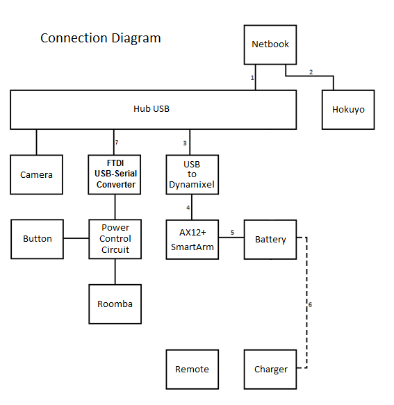
Connections Diagram
Components, connectors list:
1 - Netbook - Acer EEEPC
3 USB Female
2 - Hub USB
1 	USB		Male
4 	USB		Female
3 - Hokuyo
1 Mini - USB Female
4 - Camera
1 USB Male
5 - USB-to-Dynamixel
1	USB		Male
1	3-pin AX12	Male
1	4-pin		Female
6 - AX12+ Smart Arm
1	3-pin AX12	Male
1	P4		Female
7 - Battery
1 P4 Female
8 - Button
1 2-pin Female
9 - Power Control Circuit
1	DB-25		Male
1	2-pin		Male
1	6-pin contact	Male
10 - Roomba
1 DB-25 Female
11 - Charger
1 p4 Male
12 - FTDI USB-Serial Converter
1	6-pin contact	Female
1	Mini-USB	Female
Cables list:
1 - USB Extension			Female - Male
2 - USB Y Cable				Double USB Male - Mini-USB
3 - USB Extension			Female - Male
4 - 3-Wire AX12+			Female - Female
5 - P4 Cable				Undefined - Male
6 - Charger Cable			Undefined - P4 Male
7 - Mini USB cable			USB Male - Mini-USB Male
Battery performance characteristics
Ni-MH Battery (Arms):
Model: Saft Ni-MH
Minimum capacity: 1500 mAh
Configuration: 9.6V/ 8CELL
Pack weight: 0.430 kg (0.95 lb)
Pack size : 100 x 58 x 15 mm
Lithium Ion Battery (Netbook):
Model: Asus AL31-1005
Minimum capacity: 2600mAh
Voltage: 10.95Vdc
Ni-MH Battery (Roomba):
Minimum capacity: 3000mAh
Voltage: 14,4Vdc
Battery Operation
Each arm is going to be powered by a Ni-MH battery instead of the lithium polymer battery. This change was made because lithium polymer batteries are very expensive and the recharge is complicated.
To charge the battery, all we need is a power source with controlled current.
Without the lithium polymer battery, the fuel gauge is no longer needed. “It is going to be used a fuel gauge based on the bq20zXX series, produced by Texas Instruments, it constantly reads the battery status such as available charge, battery voltage, current and temperature. The Fuel Gauge circuit uses SMBus 1.1, in order to have a computer communicating with it, a circuit capable of converting SMBus to USB is needed. At first, it is going to used the EV2300, also produced by Texas Instruments, it is included in some of the bq20zXX Evaluation Modules, sold ready to use, it also includes a software to use with the fuel gauge.”
Roomba's Power Control
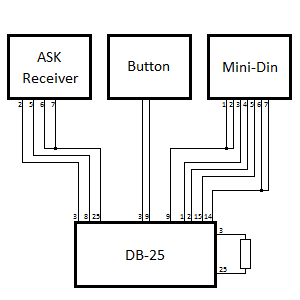
The project's specifications don't allow access to Roomba's power button, to solve that, we need to place an external button.Through the DB-25 port we have access to roomba's battery and the power toggle, when there is a transition from low to high the roomba changes its on/off status. A pull-down resistor is connected from ground to the power toggle pin and the button is connected to the roomba's battery pin.
There will be the option of turning Roomba off remotely, in order to make that possible, an ASK receiver module is going to be included in the power control circuit and an ASK transmitter module will be on a remote controller board.
The Mini-din port used to communicate with the Notebook is not in a good place, we can connect the cables coming from the computer to the DB-25 port, that is going to be on the power control circuit too.
By doing that, we integrated some isolated circuits in a single box connected to the port located inside the empty space on Roomba. The fuel gauging system, though it's not connected to Roomba directly, will be inside that box too, that increases the free space and makes connections easier.

